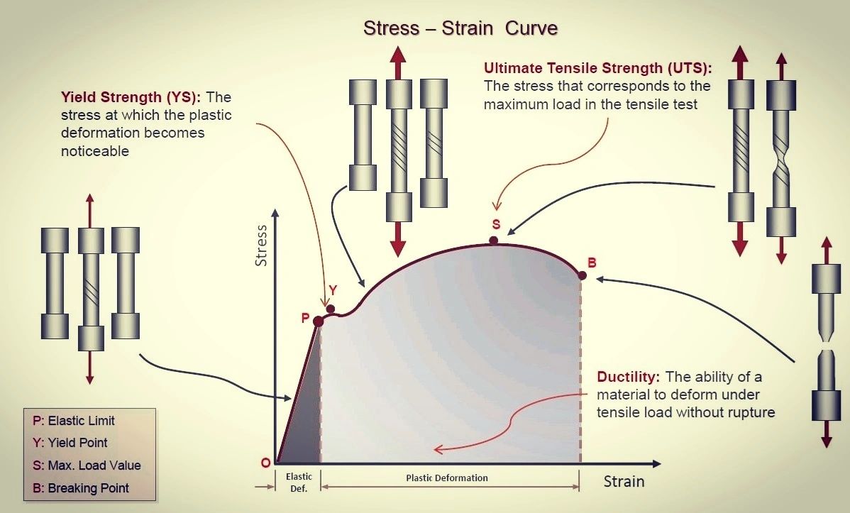
Comparison of stress–strain diagram of steel-Aluminum-Cast iron
True Stress – True Strain Curve: Part Two
Definition Generally speaking, curves representing the relationship between stress and strain in any form of deformation can be regarded as stress–strain curves. The stress and strain can be normal, shear, or mixture, and can also can be uniaxial, biaxial, or multiaxial, even change with time.

Source Image: ar.pinterest.com
Download Image
Stressstrain Diagram Suppose that a metal specimen be placed in tension-compression-testing machine. As the axial load is gradually increased in increments, the total elongation over the gauge length is measured at each increment of the load and this is continued until failure of the specimen takes place.

Source Image: studymeta.com
Download Image
The stress strain diagram for a steel alloy having an original diameter of 12 mm and a gauge length of 50 mm is given in the figure. IF the specimen is loaded StressStrain diagram for steel explained Tutor Jack Ph 9.97K subscribers 789 views 2 years ago Fundamentals of Structural Steel Design This video explains the behavior of the stress–strain

Source Image: m.youtube.com
Download Image
The Stress Strain Diagram For A Steel Alloy
StressStrain diagram for steel explained Tutor Jack Ph 9.97K subscribers 789 views 2 years ago Fundamentals of Structural Steel Design This video explains the behavior of the stress–strain Example #6.1. The stress–strain diagram for a steel alloy having an initial diameter of 12.5 mm and an initial gauge length of 50mm is provided in the figure. Determine the approximate modulus of elasticity for the material, the load on the specimen that causes yielding, and the ultimate load that the specimen will support. Example #6.2.
Problem 3-10/3-11/3-12/ Engineering Mechanics Materials. – YouTube
The engineering measures of stress and strain, denoted in this module as σe and εe respectively, are determined from the measured the load and deflection using the original specimen cross-sectional area A0 A 0 and length L0 L 0 as. σe = P A0,ϵe = δ L0 (1.4.1) (1.4.1) σ e = P A 0, ϵ e = δ L 0. When the stress σe is plotted against the 2- Easy approach to Stress strain relationship. – Engineering Oasis

Source Image: magedkamel.com
Download Image
02.1-1 Stress strain diagram – EXAMPLE – YouTube The engineering measures of stress and strain, denoted in this module as σe and εe respectively, are determined from the measured the load and deflection using the original specimen cross-sectional area A0 A 0 and length L0 L 0 as. σe = P A0,ϵe = δ L0 (1.4.1) (1.4.1) σ e = P A 0, ϵ e = δ L 0. When the stress σe is plotted against the

Source Image: m.youtube.com
Download Image
True Stress – True Strain Curve: Part Two Comparison of stress–strain diagram of steel-Aluminum-Cast iron

Source Image: totalmateria.com
Download Image
The stress strain diagram for a steel alloy having an original diameter of 12 mm and a gauge length of 50 mm is given in the figure. IF the specimen is loaded Stressstrain Diagram Suppose that a metal specimen be placed in tension-compression-testing machine. As the axial load is gradually increased in increments, the total elongation over the gauge length is measured at each increment of the load and this is continued until failure of the specimen takes place.

Source Image: homework.study.com
Download Image
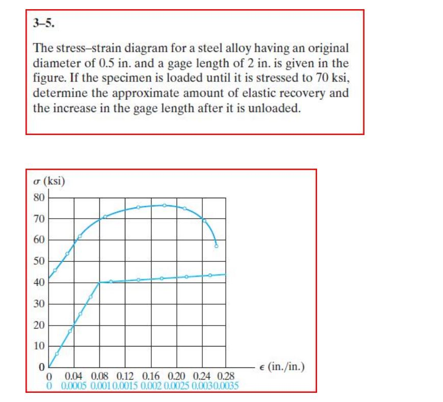
The stress strain diagram for a steel alloy having an original diameter of 0.5 in and a gauge length of 2 in is given in ht e figure. If the specimen is The stress–strain diagram for a steel alloy having an original diameter of 0.5in. and a gagelength of 2in. is shown in the figure below. (Figure 1)A. Find the modulus of resilience in inch-Ibs/cubic inch.B. Find the modulus of otughness.

Source Image: homework.study.com
Download Image
Pin on Material science StressStrain diagram for steel explained Tutor Jack Ph 9.97K subscribers 789 views 2 years ago Fundamentals of Structural Steel Design This video explains the behavior of the stress–strain

Source Image: ar.pinterest.com
Download Image
Solved The stress -strain diagram for a steel alloy having | Chegg.com Example #6.1. The stress–strain diagram for a steel alloy having an initial diameter of 12.5 mm and an initial gauge length of 50mm is provided in the figure. Determine the approximate modulus of elasticity for the material, the load on the specimen that causes yielding, and the ultimate load that the specimen will support. Example #6.2.

Source Image: chegg.com
Download Image
02.1-1 Stress strain diagram – EXAMPLE – YouTube
Solved The stress -strain diagram for a steel alloy having | Chegg.com Definition Generally speaking, curves representing the relationship between stress and strain in any form of deformation can be regarded as stress–strain curves. The stress and strain can be normal, shear, or mixture, and can also can be uniaxial, biaxial, or multiaxial, even change with time.
The stress strain diagram for a steel alloy having an original diameter of 12 mm and a gauge length of 50 mm is given in the figure. IF the specimen is loaded Pin on Material science The stress–strain diagram for a steel alloy having an original diameter of 0.5in. and a gagelength of 2in. is shown in the figure below. (Figure 1)A. Find the modulus of resilience in inch-Ibs/cubic inch.B. Find the modulus of otughness.